HPSDR Hermes
J16 Breakout Board


PRODUCTION INFORMATION -- 15 FEBRUARY 2014
This board provides access to the audio and keying lines available on the HPSDR "Hermes" transceiver's 26-pin J16 rear panel connector. Specifically, it provides these outputs:
- Right Speaker to a 3.5mm (1/8 inch) audio jack (ground isolated)
- Headphones to a 3.5mm audio jack
- Line Out to a 3.5mm audio jack
- Open-collector outputs 1 throu 7 to a 10 pin header
- Amp Key to a 3.5mm audio jack as well as a 2-pin header
and these inputs:
- PTT from a 3.5mm audio jack as well as a 2-pin header
- Line In from a 3.5mm audio jack
The board and parts kit is now available from TAPR.
The board is designed to be as small as possible (about 1.25 x 1.5 inches) because there is little room on either side of J16, and I didn't want to increase the required clearance behind the radio any more than I had to.
It plugs directly into J16 and extends horizontally behind the radio. On the left side, CON1 is a right-angle, PCB mount, female, unkeyed, 26 pin connector that mates with J16. It mounts on the top of the PCB and has its pinout mirrored to match the actual layout of J16 (which is NOT the same as shown in the Hermes schematic!). If the pinout doesn't make sense, remember that it's a right-angle connector, so the row of pins closest to the edge of the board ends up connecting to the bottom row of J16.
Layout
There are five 3.5mm audio jacks; three are on the top of the board, and the other two are on the bottom. The spacing allows cables to be plugged into all five jacks, but it can be a tight squeeze. If you can use cables with thin connector shells, you'll find an easier fit.
(Click on the image to see a full-sized version.)

The 10-pin header (SV1) carries the 7 open-collector output signals on pins 1 though 7. The "open collector reference/flyback diodes" signal is on pin 8. Pins 9 and 10 (which are oriented nearest to the board edge) are ground.
Two-pin headers labeled PTT_IN and PTT_OUT provide access to the PTT and amp keying signals. On both headers, the ground pin is closest to the edge of the board. PTT_IN is closest to the radio; PTT_OUT is closest to the row of 3.5mm jacks.
Somewhere along the way, a design error crept in. The intention originally was to allow the LINE_IN jack to optionally use one circuit for another PTT_IN signal (so that it would work the same way as the Hermes MIC input does by default). However, I goofed up and the PTT_OUT (amp keying) signal got routed there instead. Sorry about that.
Assembly Notes
Some notes on building the Hermes breakout board:
-
There are pads to install surface mount 0805 bypass caps on the analog
lines. These are not required in most instances, and are not
included in the TAPR kit. The pads are provided more for "good practice"
than anything else. If you do install them, 1000pf is a reasonable value.
-
If you don't need the open-collector control signals, I'd suggest that
you not install the ten pin header at SV1. That will provide greater
clearance if you want to connect to the ANT3 jack on the ANAN-10, and avoids
the possibility of accidentally shorting those pins.
-
I suggest that you install parts in the following order:
- Bypass caps (if used) on the top of the board.
- 3.5mm jacks on the top of the board.
IMPORTANT: Solder alone is not enough to secure these parts to the board. Use a couple of dabs of Superglue between the plastic and the board before soldering. And, make sure you get a solid solder connection on the tab-style pins. If you do not do so, it will be very easy to "pop" off the jacks from torque while connecting or disconnecting cables. You Have Been Warned. - 26 pin right-angle connector on the top of the board.
- Bypass caps (if used) in the bottom of the board.
- 3.5mm jacks on the bottom of the board.
IMPORTANT: See note above. You Have Been Warned Again. - Jumpers and headers on the top of the board.
If you happen to use a TenTec 418 amplifier connected to the PTT_KEY jack with a standard stereo cable, set JP1 to pins 1-2. In other cases, see the schematic below for information on jumper setting.
Schematic
(Click on the image to see a full-sized version.) 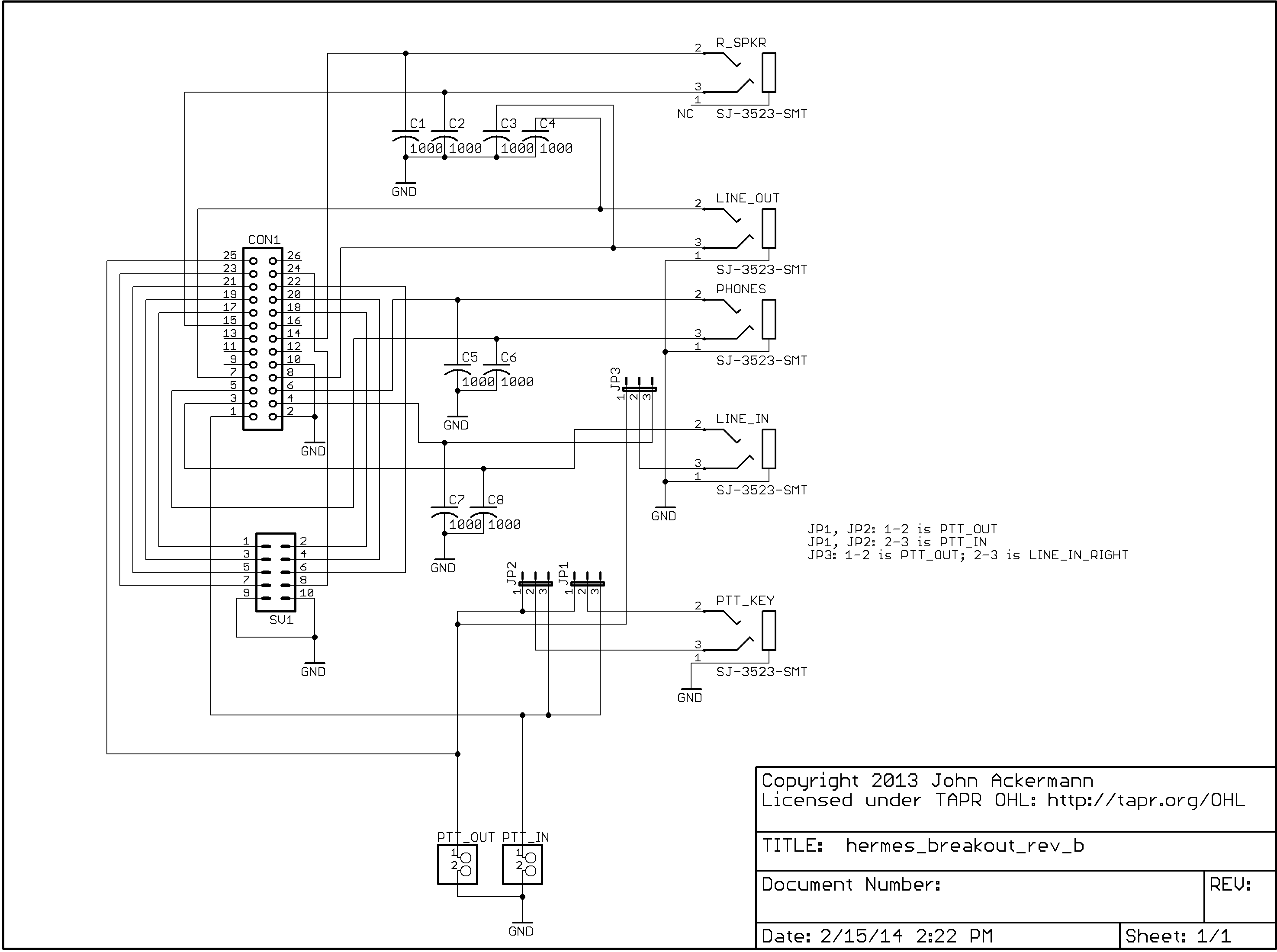
Top and Bottom Routing
(Click on the images to see full-sized versions.) 
